


Wireless Communication with XBee Radios
Wireless Communication with XBee Radios
Practical Example
Minimum parts needed: (see Tom Igoe's parts list for additional details)
Prototyping board (breadboard)
Power supply connector
5-15VDC power supply
Assorted wires
5V regulator
3.3V regulator
PIC 18F452
2 XBee ZigBee OEM RF Modules
2 PCB (printed circuit board) breakout boards for XBee (gerber files by Tom Igoe)
Male headers
LEDs
Switch
10µf capacitors
1µf capacitors
10Kohm resistors
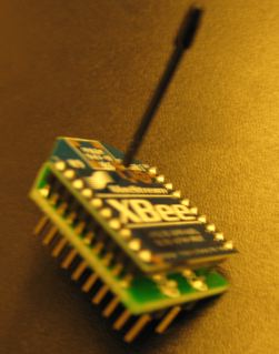
Step 1:
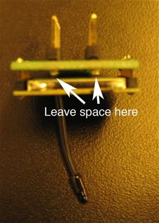
Solder the XBee RF Module to the PCB breakout board as shown. The white silkscreened lettering should face downward, away from the XBee Module. Be sure to leave enough space so that the headers do not touch the back of the module.


XBee soldered to custom breakout board. Be sure to leave enough space between the
XBee and the metal headers so that they don't touch and short out.
Step 2:
Set up two breadboards with a PIC on each. You'll need to add a 3.3 Volt regulator to each board, for powering the XBee radios. The 3.3V regulator used in this example is arranged (from left to right) Ground-Output-Input, which is different from the 5 Volt one.
PIC18F452 running on 5 Volts. XBee running on 3.3 Volt regulator at center of breadboard.
Step 3:
Connect 3.3 Volt power to pin 1 of the XBee, ground to pin 10, RC7 from the PIC to pin 2 and RC6 to pin 3 as shown. You may also want to add LEDs to pins 6, 13 and 15 for some status feedback.
XBee connected to 3.3 Volt power and common ground. The XBee tx pin is connected to rx on PIC, and XBee rx pin is connected to tx on PIC.
Green LED shows that XBee is powered on and not in sleep mode, yellow LED flashes except when
in AT command mode, and red LED lights when receiving RF data from another XBee radio.
Step 4:
Program one microcontroller using this sending code:
' serial out is on portc.6
' serial in is on portc.7
' a digital input is on portb.0
'set a constant with the baudmode 9600-8-n-1-true (non-inverted):
true9600 con 84
' a byte to send out data:
thisByte var byte
' set portb.0 to input:
input portb.0
' set portd.1 to output for status light:
output portd.1
configure: ' label to jump back to if configuration times out
' blink status light once on startup
High portd.1
pause 200
low portd.1
PAUSE 200
' for some reason it seems to help to send an arbitrary character first
' then pause for the guard time before requesting command mode
serout2 portc.6, true9600, ["X"]
pause 1500
' put the XBee in command mode
serout2 portc.6, true9600, ["+++"]
' wait for a response from the XBee for 2000 ms, or start
' over at the configure label if no valid response comes
SERIN2 portc.7, true9600, 2000, configure, [WAIT ("OK")]
' set the PAN (personal area network) ID number
' this example uses 0x3330, but you'll want to choose your own
' unique hexadecimal number between 0x0 and 0xFFFE
serout2 portc.6, true9600, ["ATID3330,"]
' set the Destination High to 0x0
' to select 16 bit addressing mode. These addresses can
' be assigned and changed by sending commands from a microcontroller
serout2 portc.6, true9600, ["DH0,"]
' set the Destination Low (16 bit address)
' this example uses 0x0 for send and 0x1 for receive but you'll
' want to choose your own hexadecimal numbers between 0x0 and 0xFFFE
serout2 portc.6, true9600, ["DL1,"]
' exit command mode
serout2 portc.6, true9600, ["CN",13]
' wait for a response from the XBee for 2000 ms, or start
' over at the configure label if no valid response comes
SERIN2 portc.7, true9600, 2000, configure, [WAIT ("OK")]
main:
' read the switch:
thisByte = portb.0
' convert it to a readable ASCII value, send it out the serial port:
serout2 portc.6, true9600, [DEC thisByte]
goto main
Here is the same code for Arduino: XBee_Send_Example.pde
Step 5:
Program the other microcontroller using this receiving code:
' serial out is on portc.6
' serial in is on portc.7
' a digital input is on portb.0
'set a constant with the baudmode 9600-8-n-1-true (non-inverted):
true9600 con 84
' set a constant for timeout while waiting for serial input
timeout CON 2000
' a byte to receive data:
inByte var byte
' set portb.1 to output:
OUTPUT portb.1
' set portd.1 to output for status light:
output portd.1
configure: ' label to jump back to if configuration times out
' blink status light once on startup
High portd.1
pause 200
low portd.1
PAUSE 200
' for some reason it seems to help to send an arbitrary character first
' then pause for the guard time before requesting command mode
serout2 portc.6, true9600, ["X"]
pause 1100
' put the XBee in command mode
serout2 portc.6, true9600, ["+++"]
' wait for a response from the XBee for 2000 ms, or start
' over at the configure label if no valid response comes
SERIN2 portc.7, true9600, timeout, configure, [WAIT ("OK")]
' set the PAN (personal area network) ID number
' this example uses 0x3330, but you'll want to choose your own
' unique hexadecimal number between 0x0 and 0xFFFE
serout2 portc.6, true9600, ["ATID3330,"]
' set the MY (16 bit address)
' this example uses 0x0 for send and 0x1 for receive but you'll
' want to choose your own hexadecimal numbers between 0x0 and 0xFFFE
serout2 portc.6, true9600, ["MY1,"]
' exit command mode
serout2 portc.6, true9600, ["CN",13]
' wait for a response from the XBee for 2000 ms, or start
' over at the configure label if no valid response comes
SERIN2 portc.7, true9600, timeout, configure, [WAIT ("OK")]
main:
' get any incoming data:
SERIN2 portc.7, true9600, timeout, nodata, [DEC inByte]
' light the LED if a 1 has been received
if inByte == 1 THEN
HIGH portb.1
' douse the LED if anything else was received
ELSE
LOW portb.1
ENDIF
nodata: ' label to jump to if no data was received
goto main
Here is the same code for Arduino: XBee_Receive_Example.pde
Step 6:
Attach a switch to RB0 of the sending board, and an LED to RB1 of the receiving board. Close the switch and the LED should light up.
Step 7:
Change your code so that there's a switch and light on both boards, and closing either switch lights the light on the other board. This should help familiarize you with how the radios communicate.
There's PLENTY more features on the XBee including broadcast modes, data enveloping and mesh networking. Once you're comfortable with the basics, you may want to explore further.
http://www.faludi.com/itp_coursework/meshnetworking/XBee/XBee_example.html
Practical Example
Minimum parts needed: (see Tom Igoe's parts list for additional details)
Prototyping board (breadboard)
Power supply connector
5-15VDC power supply
Assorted wires
5V regulator
3.3V regulator
PIC 18F452
2 XBee ZigBee OEM RF Modules
2 PCB (printed circuit board) breakout boards for XBee (gerber files by Tom Igoe)
Male headers
LEDs
Switch
10µf capacitors
1µf capacitors
10Kohm resistors
Step 1:
Solder the XBee RF Module to the PCB breakout board as shown. The white silkscreened lettering should face downward, away from the XBee Module. Be sure to leave enough space so that the headers do not touch the back of the module.
XBee soldered to custom breakout board. Be sure to leave enough space between the
XBee and the metal headers so that they don't touch and short out.
Step 2:
Set up two breadboards with a PIC on each. You'll need to add a 3.3 Volt regulator to each board, for powering the XBee radios. The 3.3V regulator used in this example is arranged (from left to right) Ground-Output-Input, which is different from the 5 Volt one.
PIC18F452 running on 5 Volts. XBee running on 3.3 Volt regulator at center of breadboard.
Step 3:
Connect 3.3 Volt power to pin 1 of the XBee, ground to pin 10, RC7 from the PIC to pin 2 and RC6 to pin 3 as shown. You may also want to add LEDs to pins 6, 13 and 15 for some status feedback.
XBee connected to 3.3 Volt power and common ground. The XBee tx pin is connected to rx on PIC, and XBee rx pin is connected to tx on PIC.
Green LED shows that XBee is powered on and not in sleep mode, yellow LED flashes except when
in AT command mode, and red LED lights when receiving RF data from another XBee radio.
Step 4:
Program one microcontroller using this sending code:
' serial out is on portc.6
' serial in is on portc.7
' a digital input is on portb.0
'set a constant with the baudmode 9600-8-n-1-true (non-inverted):
true9600 con 84
' a byte to send out data:
thisByte var byte
' set portb.0 to input:
input portb.0
' set portd.1 to output for status light:
output portd.1
configure: ' label to jump back to if configuration times out
' blink status light once on startup
High portd.1
pause 200
low portd.1
PAUSE 200
' for some reason it seems to help to send an arbitrary character first
' then pause for the guard time before requesting command mode
serout2 portc.6, true9600, ["X"]
pause 1500
' put the XBee in command mode
serout2 portc.6, true9600, ["+++"]
' wait for a response from the XBee for 2000 ms, or start
' over at the configure label if no valid response comes
SERIN2 portc.7, true9600, 2000, configure, [WAIT ("OK")]
' set the PAN (personal area network) ID number
' this example uses 0x3330, but you'll want to choose your own
' unique hexadecimal number between 0x0 and 0xFFFE
serout2 portc.6, true9600, ["ATID3330,"]
' set the Destination High to 0x0
' to select 16 bit addressing mode. These addresses can
' be assigned and changed by sending commands from a microcontroller
serout2 portc.6, true9600, ["DH0,"]
' set the Destination Low (16 bit address)
' this example uses 0x0 for send and 0x1 for receive but you'll
' want to choose your own hexadecimal numbers between 0x0 and 0xFFFE
serout2 portc.6, true9600, ["DL1,"]
' exit command mode
serout2 portc.6, true9600, ["CN",13]
' wait for a response from the XBee for 2000 ms, or start
' over at the configure label if no valid response comes
SERIN2 portc.7, true9600, 2000, configure, [WAIT ("OK")]
main:
' read the switch:
thisByte = portb.0
' convert it to a readable ASCII value, send it out the serial port:
serout2 portc.6, true9600, [DEC thisByte]
goto main
Here is the same code for Arduino: XBee_Send_Example.pde
Step 5:
Program the other microcontroller using this receiving code:
' serial out is on portc.6
' serial in is on portc.7
' a digital input is on portb.0
'set a constant with the baudmode 9600-8-n-1-true (non-inverted):
true9600 con 84
' set a constant for timeout while waiting for serial input
timeout CON 2000
' a byte to receive data:
inByte var byte
' set portb.1 to output:
OUTPUT portb.1
' set portd.1 to output for status light:
output portd.1
configure: ' label to jump back to if configuration times out
' blink status light once on startup
High portd.1
pause 200
low portd.1
PAUSE 200
' for some reason it seems to help to send an arbitrary character first
' then pause for the guard time before requesting command mode
serout2 portc.6, true9600, ["X"]
pause 1100
' put the XBee in command mode
serout2 portc.6, true9600, ["+++"]
' wait for a response from the XBee for 2000 ms, or start
' over at the configure label if no valid response comes
SERIN2 portc.7, true9600, timeout, configure, [WAIT ("OK")]
' set the PAN (personal area network) ID number
' this example uses 0x3330, but you'll want to choose your own
' unique hexadecimal number between 0x0 and 0xFFFE
serout2 portc.6, true9600, ["ATID3330,"]
' set the MY (16 bit address)
' this example uses 0x0 for send and 0x1 for receive but you'll
' want to choose your own hexadecimal numbers between 0x0 and 0xFFFE
serout2 portc.6, true9600, ["MY1,"]
' exit command mode
serout2 portc.6, true9600, ["CN",13]
' wait for a response from the XBee for 2000 ms, or start
' over at the configure label if no valid response comes
SERIN2 portc.7, true9600, timeout, configure, [WAIT ("OK")]
main:
' get any incoming data:
SERIN2 portc.7, true9600, timeout, nodata, [DEC inByte]
' light the LED if a 1 has been received
if inByte == 1 THEN
HIGH portb.1
' douse the LED if anything else was received
ELSE
LOW portb.1
ENDIF
nodata: ' label to jump to if no data was received
goto main
Here is the same code for Arduino: XBee_Receive_Example.pde
Step 6:
Attach a switch to RB0 of the sending board, and an LED to RB1 of the receiving board. Close the switch and the LED should light up.
Step 7:
Change your code so that there's a switch and light on both boards, and closing either switch lights the light on the other board. This should help familiarize you with how the radios communicate.
There's PLENTY more features on the XBee including broadcast modes, data enveloping and mesh networking. Once you're comfortable with the basics, you may want to explore further.
http://www.faludi.com/itp_coursework/meshnetworking/XBee/XBee_example.html
Temperature sensors
What is a temperature sensor?
An analog temperature sensor is pretty easy to explain, its a chip that tells you what the ambient temperature is!
These sensors use a solid-state technique to determine the temperature. That is to say, they dont use mercury (like old thermometers), bimetalic strips (like in some home thermometers or stoves), nor do they use thermistors (temperature sensitive resistors). Instead, they use the fact as temperature increases, the votage across a diode increases at a known rate. (Technically, this is actually the voltage drop between the base and emitter - the Vbe - of a transistor. By precisely amplifying the voltage change, it is easy to genereate an analog signal that is directly proportional to temperature. There have been some improvements on the technique but, essentially that is how temperature is measured.
Because these sensors have no moving parts, they are precise, never wear out, don't need calibration, work under many environmental conditions, and are consistant between sensors and readings. Moreover they are very inexpensive and quite easy to use
Some basic stats
These stats are for the temperature in the Adafruit shop, the Analog Devices TMP36 (-40 to 150C). Its very similar to the LM35/TMP35 (celsius output) and LM34/TMP34 (farenheit output). The reason we went with the '36 instead of the '35 or '34 is that this sensor has a very wide range and doensn't require a negative voltage to read sub-zero temperatures. Otherwise, the functionality is basically the same.
Size: TO-92 package (about 0.2" x 0.2" x 0.2") with three leads
Price: $2.00 at the Adafruit shop
Temperature range: -40°C to 150°C / -40°F to 302°F
Output range: 0.1V (-40°C) to 2.0V (150°C) but accuracy decreases after 125°C
Power supply: 2.7V to 5.5V only, 0.05 mA current draw
Datasheet
How to measure temperature!
Using the TMP36 is easy, simply connect the left pin to power (2.7-5.5V) and the right pin to ground. Then the middle pin will have an analog voltage that is directly proportional (linear) to the temperature. The analog voltage is independant of the power supply.
To convert the voltage to temperature, simply use the basic formula:
Temp in °C = [(Vout in mV) - 500] / 10
So for example, if the voltage out is 1V that means that the temperature is ((1000 mV - 500) / 10) = 50 °C
If you're using a LM35 or similar, use line 'a' in the image above and the formula: Temp in °C = (Vout in mV) / 10
Testing your temperature sensor
Testing these sensors is pretty easy but you'll need a battery pack or power supply.
Connect a 2.7-5.5V power supply (2-4 AA batteries work fantastic) so that ground is connected to pin 3 (right pin), and power is connected to pin 1 (left pin)
Then connect your multimeter in DC voltage mode to ground and the remaining pin 2 (middle). If you've got a TMP36 and its about room temperature (25°C), the voltage should be about 0.75V. Note that if you're using a LM35, the voltage will be 0.25V
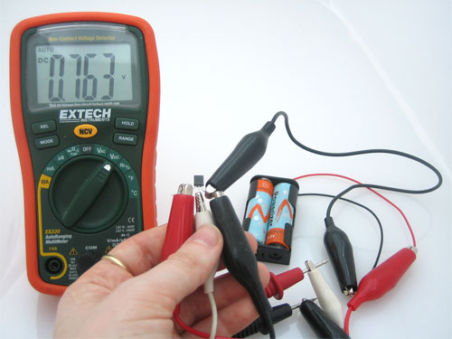
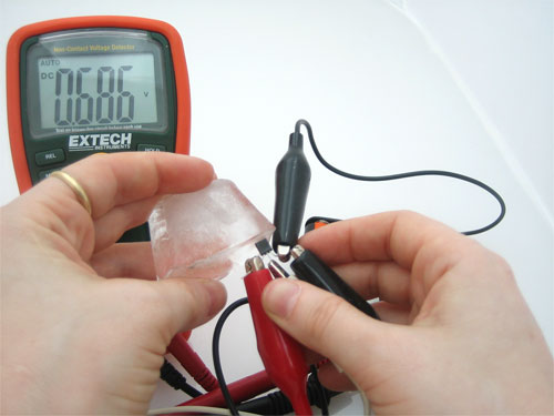
You can change the voltage range by pressing the plastic case of the sensor with your fingers, you will see the temperature/voltage rise.
 Connecting to your temperature sensor
These sensors have little chips in them and while they're not that delicate, they do need to be handled properly. Be careful of static electricity when handling them and make sure the power supply is connected up correctly and is between 2.7 and 5.5V DC - so don't try to use a 9V battery!
breadboarded to-92
They come in a "TO-92" package which means the chip is housed in a plastic hemi-cylinder with three legs. The legs can be bent easily to allow the sensor to be plugged into a breadboard. You can also solder to the pins to connect long wires. If you need to waterproof the sensor, you can see below for an Instructable for how to make an excellent case.
Project examples
Some of these projects use thermistors (resistors that change their resistance based on temperature), but can very easily be adapted to to a solid state sensor like the TMP36
Reading the analog temperature data
Unlike the FSR or photocell sensors we have looked at, the TMP36 and friends doesn't act like a resistor. Because of that, there is really only one way to read the temperature value from the sensor, and that is plugging the output pin directly into an Analog (ADC) input.
Remember that you can use anywhere between 2.7V and 5.5V as the power supply. For this example I'm showing it with a 5V supply but note that you can use this with a 3.3v supply just as easily. No matter what supply you use, the analog voltage reading will range from about 0V (ground) to about 1.75V.
If you're using a 5V Arduino, and connecting the sensor directly into an Analog pin, you can use these formulas to turn the 10-bit analog reading into a temperature:
Voltage at pin in milliVolts = (reading from ADC) * (5000/1024)
This formula converts the number 0-1023 from the ADC into 0-5000mV (= 5V)
If you're using a 3.3V Arduino, you'll want to use this:
Voltage at pin in milliVolts = (reading from ADC) * (3300/1024)
This formula converts the number 0-1023 from the ADC into 0-3300mV (= 3.3V)
Then, to convert millivolts into temperature, use this formula:
Centigrade temperature = [(analog voltage in mV) - 500] / 10
Simple thermometer
This example code for Arduino shows a quick way to create a temperature sensor, it simply prints to the serial port what the current temperature is in both Celsius and Fahrenheit
//TMP36 Pin Variables
int sensorPin = 0; //the analog pin the TMP36's Vout (sense) pin is connected to
//the resolution is 10 mV / degree centigrade with a
//500 mV offset to allow for negative temperatures
/*
* setup() - this function runs once when you turn your Arduino on
* We initialize the serial connection with the computer
*/
void setup()
{
Serial.begin(9600); //Start the serial connection with the computer
//to view the result open the serial monitor
}
void loop() // run over and over again
{
//getting the voltage reading from the temperature sensor
int reading = analogRead(sensorPin);
// converting that reading to voltage, for 3.3v arduino use 3.3
float voltage = reading * 5.0 / 1024;
// print out the voltage
Serial.print(voltage); Serial.println(" volts");
// now print out the temperature
float temperatureC = (voltage - 0.5) * 100 ; //converting from 10 mv per degree wit 500 mV offset
//to degrees ((volatge - 500mV) times 100)
Serial.print(temperatureC); Serial.println(" degress C");
// now convert to Fahrenheight
float temperatureF = (temperatureC * 9 / 5) + 32;
Serial.print(temperatureF); Serial.println(" degress F");
delay(1000); //waiting a second
}
Auto-calibrating supply-independent thermometer
This example is similar to the one above except that now we use a special trick where we read the analog value of a fixed reference voltage inside the chip and then use that to make a precise calculation. This also means it will work right no matter what voltage the Arduino is running at!
//TMP36 Pin Variables
int sensorPin = 0; //the analog pin the TMP36's Vout (sense) pin is connected to
//the resolution is 10 mV / degree centigrade with a
//500 mV offset to allow for negative temperatures
#define BANDGAPREF 14 // special indicator that we want to measure the bandgap
/*
* setup() - this function runs once when you turn your Arduino on
* We initialize the serial connection with the computer
*/
void setup()
{
Serial.begin(9600); //Start the serial connection with the computer
//to view the result open the serial monitor
delay(500);
}
void loop() // run over and over again
{
// get voltage reading from the secret internal 1.05V reference
int refReading = analogRead(BANDGAPREF);
Serial.println(refReading);
// now calculate our power supply voltage from the known 1.05 volt reading
float supplyvoltage = (1.05 * 1024) / refReading;
Serial.print(supplyvoltage); Serial.println("V power supply");
//getting the voltage reading from the temperature sensor
int reading = analogRead(sensorPin);
// converting that reading to voltage
float voltage = reading * supplyvoltage / 1024;
// print out the voltage
Serial.print(voltage); Serial.println(" volts");
// now print out the temperature
float temperatureC = (voltage - 0.5) * 100 ; //converting from 10 mv per degree wit 500 mV offset
//to degrees ((volatge - 500mV) times 100)
Serial.print(temperatureC); Serial.println(" degress C");
// now convert to Fahrenheight
float temperatureF = (temperatureC * 9 / 5) + 32;
Serial.print(temperatureF); Serial.println(" degress F");
delay(1000); //waiting a second
}
http://www.ladyada.net/learn/sensors/tmp36.html
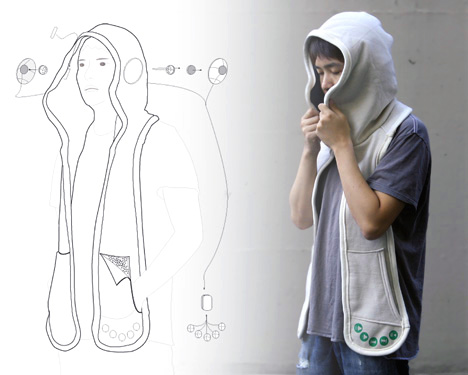
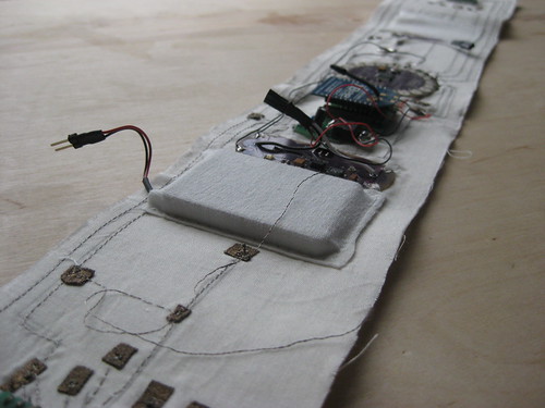
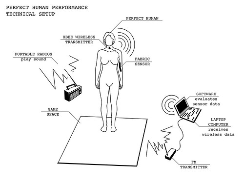
Nathalie Fougeras’ “Wearable Breast”

Usually work produced as part of a short workshop tends to be quite a routine testing of process and technique and not a fully fledged work / performance however intensive workshops can provide that opportunity to explore very directed ideas which may not have been possible for the artist due to knowledge or access to materials. Nathalie Fougeras’ wearable object / performance, Breast, What is the Breast to Choose (image above, video below) is without a doubt a fully fledged work with considerable reflection.
Created at Hybrid Scrapyard, part of the iMAL New Brave World series of workshops about the Internet of things, hybrid world and networking & locative media, the work is a technical exploration of Arduino and Xbee but conceptually explores ideas of feminine sexuality, intimacy and gratification in relation to what is most predominantly a domain (as previously media forms have been) seen through masculine eyes, the internet. The wearable device allows the artist, through self gratification, to trigger visual internet searches related to the part of the body she is touching, the breast, mimicking, parodying and subverting the male act of self-gratification and the internet’s role in the contemporary variant of that.
http://turbulence.org/blog/2009/04/15/nathalie-fougeras’-wearable-breast/
Lux : Fashion + Green Technology


Lux is an innovative technology brought to you by Mae Yokoyama, a Konstfack student, that shows the means of getting benefited from the sun and how to turn energy into beauty. This is actually a necklace that comprises solar panels in order to accumulate energy from the sun during daytime. This accumulated energy then is used to lighten the LED bulbs to give an appearance of dazzling pearls of this fashionable necklace. This useful product will help people realize the value of sun and will give a feel of elegance to fashion concerned personnel. After charging for two hours only, the pearls can remain on for a minimum of four hours.
http://www.tuvie.com/lux-fashion-green-technology
A Hood That Will Make All The Difference

Blockbuster Hollywood movies can bring on the spotlight to lesser know disease and medical conditions. For example, After Rain Man we all knew what Autism was. That story told us how autistic people suffer from impaired social interaction and communication. In children the condition is heightened with sensory disorders and even minor noises can disturb them. A recent research suggests that stimulants like music, aromatherapy, and textured toys can help alleviate the condition. This where something like the Beagle scarf-hoodie can help.
This scarf includes speakers in the hood making it the perfect soothing wrap, around the child’s ears. Furthermore, customized aroma patches along with textured inner pockets can be integrated to the scarf. Coping with as autistic child can be trying at times and if something like the Beagle can bring the child some relief, then so be it.
Designer: Leo Chao
http://www.yankodesign.com/2009/03/19/a-hood-that-will-make-all-the-difference/
Solar Powered Sun Glasses


I just saw this brilliant development by designer Hyun-Joong Kim & Kwang-Seok Jeong, created to gather and redirect solar energy used to charge your iPods, phones and other tiny gadgets. The lenses of these Self Energy Converting Sunglasses have dye solar cells, collecting energy and making it possible to feed power through the power jack at the back of the frame. “Infinite Energy: SIG”
The dye solar cell is described by the designers of the SIG as “cheap organic dye [used with] nano technology [providing] “cheap but high energy efficiency”. Inexpensive, light, and visible-ray penetrable. The lens turns sunlight rays, (rays that would otherwise harm the eye,) into electrical energy.
http://cyanatrendland.com/2008/12/23/solar-powered-sun-glasses/
Wearable computer
http://en.wikipedia.org/wiki/Wearable_computer

Wearable computers are computers that are worn on the body. They have been applied to areas such as behavioral modeling, health monitoring systems, information technologies and media development. Wearable computers are especially useful for applications that require computational support while the user's hands, voice, eyes or attention are actively engaged with the physical environment.
"Wearable computing" is an active topic of research, with areas of study including user interface design, augmented reality, pattern recognition, use of wearables for specific applications or disabilities, electronic textiles and fashion design. Many issues are common to the wearables, mobile computing, Pervasive computing, Ambient intelligence and ubiquitous computing research communities, including power management and heat dissipation, software architectures, wireless and personal area networks.
One of the main features of a wearable computer is consistency. There is a constant interaction between the computer and user, ie. there is no need to turn the device on or off. Another feature is the ability to multi-task. It is not necessary to stop what you are doing to use the device; it is augmented into all other actions. These devices can be incorporated by the user to act like a prosthetic. It can therefore be an extension of the user’s mind and/or body.
Glowing button cycling jacket


Not everyone wants to look like an athlete while cycling to work or school. This cycling-jacket, made of hemp and wool, is equipped with lots of shining bright LEDs. It looks just as good during the day as it does during the night. Embedding the Arduino Lilypad electronics in the jacket, makes it at practical as it is nice to look at!

Add a 3rd eye: ATC3K to Goggle Cam mod
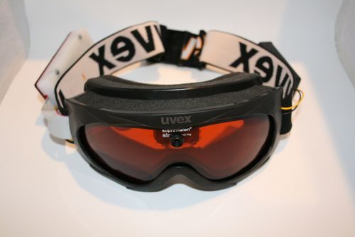
[will] submitted his ski goggle mod. he has mounted an oregon scientific atc3k digicam in his goggles. this should make recording ski trips a lot easier. most of the electronics fit just fine in the mask, though he did need to use an ide cable to extend parts of it to the custom pack mounted on the strap. we’re also curious how much wind noise he’s going to get on that microphone.
http://biobug.org/index.php/2009/05/19/add-a-3rd-eye-atc3k-to-goggle-cam-mod/
